Light Painting
Persistence of vision effects have been a minor interest of mine for several years, and I recently discovered an LED strip for sale containing 60 individually addressable RGB LEDs which I thought would be perfect for this. The strip is controlled with a one-wire serial protocol, and libraries exist for Arduino (available from Adafruit, among other places).
How it Works
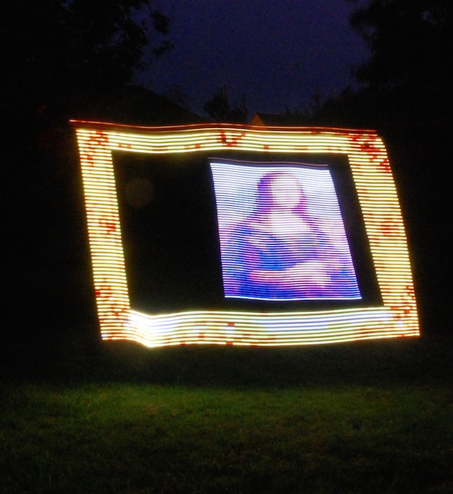
The technique is pretty simple, and is just like light-painting (where you draw with a torch or laser pointer on a long-exposure photograph to trace out shapes). In this implementation, a strip of LEDs is moved across the scene at a constant speed. The LEDs are set up to change colour and pattern to show columns of a pre-determined image and display the relevant column in space as you move. My plan is to have writing or images projected in-front of the scene to add an extra dimension and make a more fun image than I would have had before.
Setup
The hardware setup is relatively simple: An Arduino Mega board controls the system (I used the Mega because it’s got lots of flash memory compared with other Arduinos, so I can fit more/larger images onto it). A lead-acid battery from an old bike light is used to power the Arduino through its Vin connector, and a 7805 regulator provides 5VDC for the LED strip. The LEDs can draw up to 1A when fully turned on, so I used a 1A regulator with a heatsink to ensure that it didn’t overheat and cut-out – the heatsink does get rather hot after a few minutes of use. A trigger button prevents the image from being continuously displayed so that its position within the image can be controlled. Once the camera is ready, I press the trigger button and move across the scene to create the image.
The code on the Arduino is very simple. It contains three arrays, each of which corresponds to one of the primary colours red, green or blue. The code in the loop simply takes each column’s data, pushes it to the LED strip and then waits for a short amount of time (20µs in this case, which is about right for the walking pace that I used to make the light painting).
The Arduino sketch is shown below.
#include
#define DELAY 20  //time delay to display each pixel in us

#define IMAGEWIDTH 60
#define IMAGEHEIGHT 196
prog_uchar myImageR[] PROGMEM = { //Image data here};
prog_uchar myImageG[] PROGMEM = { //Image data here};
prog_uchar myImageB[] PROGMEM = { //Image data here};


// Parameter 1 = number of pixels in strip
// Parameter 2 = pin number (most are valid)
// Parameter 3 = pixel type flags, add together as needed:
//   NEO_RGB     Pixels are wired for RGB bitstream
//   NEO_GRB     Pixels are wired for GRB bitstream
//   NEO_KHZ400  400 KHz bitstream (e.g. FLORA pixels)
//   NEO_KHZ800  800 KHz bitstream (e.g. High Density LED strip)
Adafruit_NeoPixel strip = Adafruit_NeoPixel(60, 6, NEO_GRB + NEO_KHZ800);

int startButton = 12;
int watchLED = 13;
void setup()
{
  strip.begin();
  strip.show(); // Initialize all pixels to 'off'
  pinMode(startButton, INPUT);
  pinMode(watchLED, OUTPUT);
  Serial.begin(9600);
}

//Images are to be stored in a long array

void loop()
{
  int i,j;
  uint8_t Red,g,b;
  while(digitalRead(startButton) != 1)
  {
  //Hold execution here.
  for(j=0; j<IMAGEWIDTH; j++)
   {
     strip.setPixelColor(j,strip.Color(0,0,0));
    }
  strip.show();
  }
  //for each column
  j=0;

  for(i=0; i< IMAGEHEIGHT*IMAGEWIDTH; i++) {
    //for each pixel
     Red=pgm_read_byte_near(myImageR + i); //myImageR[i];
     g=pgm_read_byte_near(myImageG + i); //myImageG[i];
     b=pgm_read_byte_near(myImageB + i); //myImageB[i];

     strip.setPixelColor(j++,strip.Color(Red,g,b));

    if(i % IMAGEWIDTH == 0)
    {
      Serial.print("Showing ");
      Serial.println(i, DEC);
      strip.show();
      delay(DELAY);
      j=0;
    }
  }

} </code>
I’ve not shown the RGB data in the sketch above because it’s far too large to be able to present in a pleasing format for the web. Contact me if you really want something that I’ve used to make the images shown here.
Image Preparation
To create the image data for display on the Arduino is a three-step process. First, the image must be resized into a 60pixel tall image, and any background must be set to black (unless it needs to be shown on the resultant output). Next, the three colour channels need to be split into the correct format for the Arduino to use. Because I’m a scientist at heart, and because it was the first language I thought of when it comes to loading and manipulating data, I created a script in Octave (an open source analogue of Matlab). The script loads the bitmap image that’s ready for display on the LED strip, converts it into red, green and blue channels, and then writes the arrays in the correct format for my Arduino sketch. Finally, the output from the Octave script is pasted into the Arduino IDE and uploaded to the device.
%This GNU/Octave tool loads an image, and converts it to an array of RGB values for input into the LightScribe code on the Arduino Mega. %Set the filenames below to the input and output files, and then run the script. Once the output file is created, copy/paste it into the Arduino sketch that you're going to use.
image = imread("/Users/timini/Desktop/LightScribe/nyan.bmp");
outfilename = "nyan.txt"

%Assume that the matrix is in RGB
rows = size(image)(1)
cols = size(image)(2)


%Get the RGB components split into their own little spaces


%Need to look for consecutive 33,33,33 in the output, and replace since three of these looks like a serial command to the USB-Serial chip, which causes it to hang.

r=image(:,:,1);
g=image(:,:,2);
b=image(:,:,3);
fid=fopen(outfilename,"w");  %open file for writing

fprintf(fid, "#define IMAGEWIDTH %i\n#define IMAGEHEIGHT %i\n", rows, cols);
fprintf(fid, "prog_uchar myImageR[] PROGMEM = {\n"); %red header
string = sprintf("%i,", r(:));
string= strrep(string, "33,33,33","33,34,33"); %Catch that dodgy bug...
fprintf(fid, string);
fprintf(fid, "\n};\n");

fprintf(fid, "prog_uchar myImageG[] PROGMEM = {\n"); %green header
string = sprintf("%i,", g(:));
string= strrep(string, "33,33,33","33,34,33");
fprintf(fid, string);
fprintf(fid, "\n};\n");

fprintf(fid, "prog_uchar myImageB[] PROGMEM = {\n"); %blue header
string = sprintf("%i,", b(:));
string= strrep(string, "33,33,33","33,34,33");
fprintf(fid, string);
fprintf(fid, "\n};\n");
fclose(fid); </code>
Taking Pictures
Taking an image is pretty straightforward. The image data is uploaded to the device using the Arduino IDE, and everything is powered on. Then, I set up my camera on a tripod with a long exposure (I found 8-10 seconds is ideal) and relatively small aperture (f/16 or so on my 18-70 zoom lens). The small aperture is needed because the LEDs are quite bright and saturate the image – if I was moving faster, this wouldn’t be a problem (alternatively, the brightness of the input image could be reduced before it is processed by the Octave script). Next the camera is started on its self-timer and I got into position. When the shutter opens, I begin moving and trigger the Arduino to begin displaying the image by pressing the trigger button. Once the image has finished being shown, I let the camera complete its imaging and admire the results.
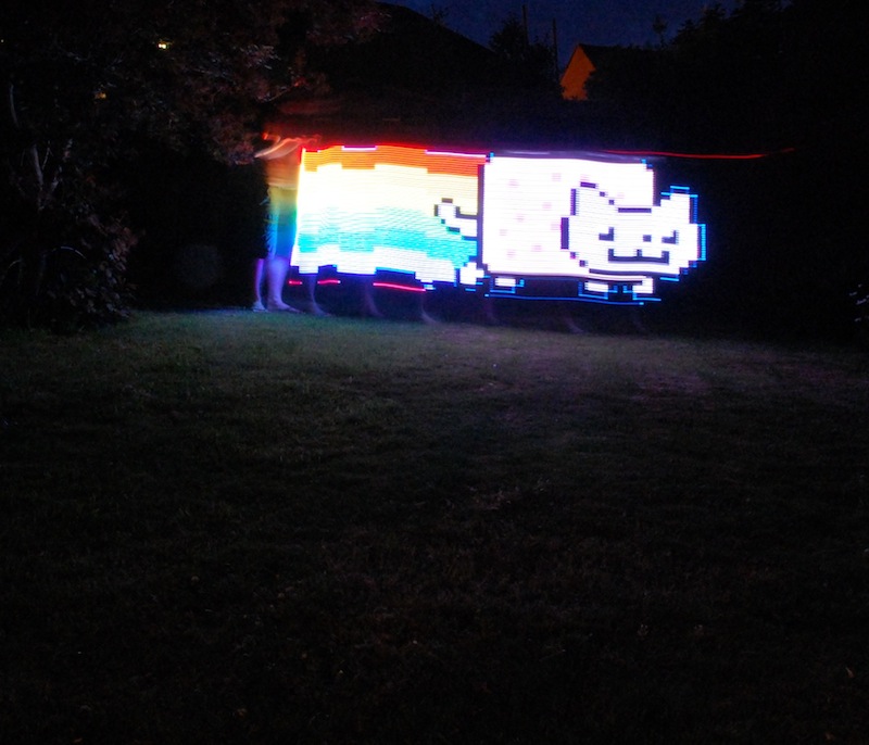
Results
There are only a couple of images that I’ve completed (on the day that I wrote this ( July 14, 2013)) and they’re show above. I’ve got a couple of ideas for some neat things that I’m going to try once the nights get a little darker, and I don’t have to go out so late to capture them.