Designing for Opto-mechanical Assemblies
I’ve done a fair amount of design for opto-mechanical assemblies over the years , and want to share some advice on the things that I’ve learnt.
Designing Around Optics
Optics are often made to small tolerances (compared to metalwork), although it’s worth noting that the form tolerance is generally high, but the dimensional tolerance may not be so tight. In other words, it’s important to check and control the shape of a particular surface on a lens or window, but much less important to control exactly where it is. This is because the majority of optics are polished, and in these kinds of processes you don’t always know exactly how much material will need to be removed to achieve the shape that you need. Once the optic has the correct surface form and finish (whether that’s flatness or a radius of curvature or whatever), polishing stops and the part is coated and shipped. If you’re designing an assembly to contain optics, it’s often really important to ensure that you can accommodate the range of diameters and thicknesses that the optics manufacturer could deliver.
Holding Optics
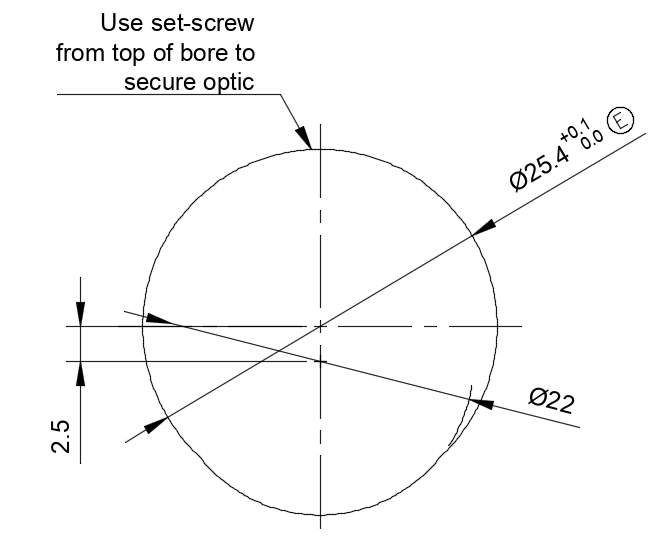
Many optical components are round, which makes them both easy and tricky to hold. If position is critical, consider a three-point grip like you would find in a bench kinematic mount where there are a pair of offset bores that allow an optic to be gripped with a setscrew and its position guaranteed (allowing for the diameter tolerances on the part). In this configuration, the centreline of the optic is controlled by its diameter and the position of the centre of the offset bore.
Examining common techniques for holding lenses, you’ll see many takes on a simple lens tube which rely on a tube with an internal diameter slightly larger than the outside diameter of the lens and a threaded ring that screws down into the bore. This is a really great solution in many cases because it allows various thicknesses of lens to be accommodated, and makes centring the lens simple because if the hole is a close fit for the optic, it fits neatly into the thread.
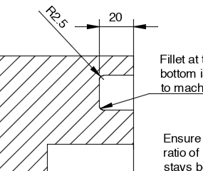
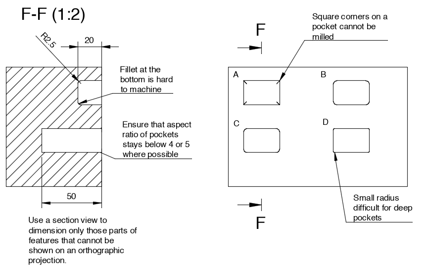
Corners in pockets and slots
Internal corners are tricky to make because the most common way to make pockets is using a milling machine, which has cylindrical tools. This means that internal pockets should have filleted corners where possible with a corner radius chosen that allows it to be made with a reasonable sized milling cutter. For pockets, try not to use a milling cutter diameter smaller than about 1/3 the depth of the pocket (i.e. for a 9mm deep hole, a minimum tool diameter would be Ø3mm, which gives R1.5 on the corners of the pocket). The bottom of pockets is best left square rather than having a radiussed fillet since this requires a ball-nosed end mill that is not great at making this type of fillet. This is because the end-mill needs to move through metal at a sufficient speed to remove the material. Since the radius of a ball-nosed mill decreases towards the ball tip, the surface speed of the cutting faces decreases and the load on the mill can increase (since fewer flutes must remove more material). This means that the cutter is more liable to break and that manufacture is more difficult. This limitation is not present if the cutter is square-ended.
Holes
Holes are usually made with a drill, and are therefore have a limited maximum depth. This is because the flutes on the side of the drill have to clear away any chips that are formed at the cutting tip. The deeper the hole, the more chance there is of the flutes becoming blocked which will cause the drill to jam and break, which will almost certainly cause damage to the part. This is an issue for the designer because it will reduce the yield that a manufacturer can produce and cause the price to be increased. Manufacturers can work around this by using ‘peck’ drilling where the drill is regularly withdrawn inside the hole during the drilling process, but this slows down the manufacture and still risks causing poor surface finish inside the hole. As a rule of thumb, try to limit hole depths (particularly blind holes to less than 3 or 4 drill diameters where possible). It’s also worth noting that the dimensional tolerance on a drilled hole is not great because the drill can wobble or bend. This means that deep, tightly tolerances holes are harder to make (and therefore more expensive). To achieve tight tolerance on the diameter, it will need to be reamed, which is an additional process step but can guarantee really close diameter dimensions.
Tapped Holes
Tapped holes need to be deep enough to hold the thread in place, but not so deep that they’re tricky to make. Taps (the tools used to make the threads) have a tapered end, so don’t cut threads along their entire length. This means that you need to allow extra depth at the bottom of a blind hole to accommodate the taper.
There are taps known as ‘plug’ taps, but these too don’t have threads all the way to the end. A rule of thumb that I use for blind holes is to limit the tapped depth to about twice the diameter of the hole (for blind holes), and drill to 3 times the finish diameter. If it’s a through-hole, then I am happy to allow 3x the hole diameter of thread on the assumption that the tap can pass all the way through.
Incorporating Electronics
Printed circuit boards can vary significantly from one to the next, both in terms of size, thickness and position of components. This is because the board itself is a laminate of several layers of fibreglass and copper which is then pressed and baked to achieve the finished result. This process is inherently not able to control thickness, and it’s not uncommon to see 0.1 or 0.2mm variation in thickness across different batches of the same PCB design. Surface mounted components are not usually positioned perfectly since they are pulled into place during the reflow step in the oven. To assemble boards, solder paste is screen-printed onto the PCB and the components are placed by machine onto the correct locations and then heated to the melting temperature of the solder. This means that the final position of the component is controlled by the surface tension in the solder when it’s liquid and that variation can occur if slightly more or less solder is deposited on a particular pad. Finally, you may have made allowances for connectors onto a PCB, but what about the cables themselves? Cable bend is tricky to get right since what looks acceptable on the CAD software can turn out to be a tight fit in the final enclosure. If you do model connectors plugged into a PCB, always try to align them so that they are fully UNplugged from their relevant connectors in addition to allowing for cable bend. This guarantees that you’ll be able to remove the connector from its socket when you need to unplug.
O-rings
O-rings are deceptively simple to use, but require great care to get right, particularly if there are large temperature ranges to accommodate. The elastomer materials can degrade at higher temperatures, and have a coefficient of thermal expansion that is often 10 times that of the metal around them. This means that adequate space needs to be left in any groove that will hold an o-ring to allow it to expend when the temperature increases. ISO3601-1 has some really useful information to calculate o-ring groove dimensions for any arbitrary o-ring size.
O-rings also need to be assembled with care, and the design should minimise any chance of catching or nicking the o-ring on sharp edges or corners whilst assembling the system. Edges leading up to an o-ring groove where the o-ring passes over should have a 15-20º lead-in to gently compress the o-ring to its final size.